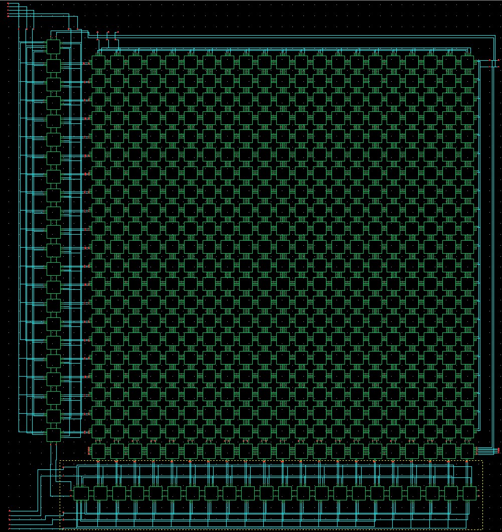
Figure 2.4.1 The full system schematic. Although details can not be seen in this view, the general concept can be conveyed. Each box represents a cell. The row of cells on the far left comprise the row decoder. The column decoder is the row of cells at the bottom of the image. The row of cells above the column decoder is the output buffer (one buffer per column). The other cells make up the 21 x 21 pixel detector array. The five-bit input to the row decoder is at the upper left (wires terminated with red pins). The input to the column decoder is at the bottom left. The output signals are at the bottom right, and power connections are at the upper right. Bias and modulation signal inputs for the array are at the top left side of the array. Bias signal inputs for the output buffer are next to the output signals.