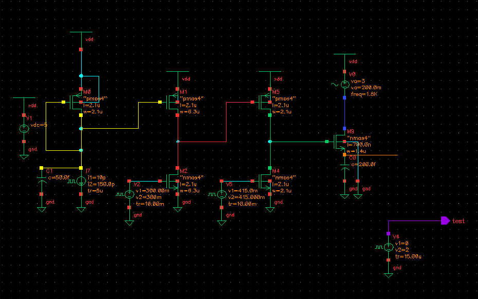
Figure 3.1 The schematic for testing the pixel circuit. The different colors on the wires denote the respective colors on the results plots.
Figure 3.1 The schematic for testing the pixel circuit. The different colors on the wires denote the respective colors on the results plots.