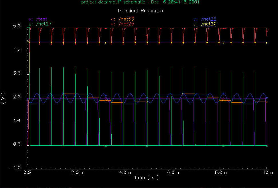
Figure 3.1.2a SImulation results for a pixel.
Yellow - Photodetector voltage
Red - Output of first inverting amplifier
Green - Output of second inverting amplifier (Sample
and Hold trigger)
Blue - Modulation signal voltage
Orange - S/H of modulation signal
Purple - showing pulse edges of photocurrent (actual
voltage has no physical meaning)
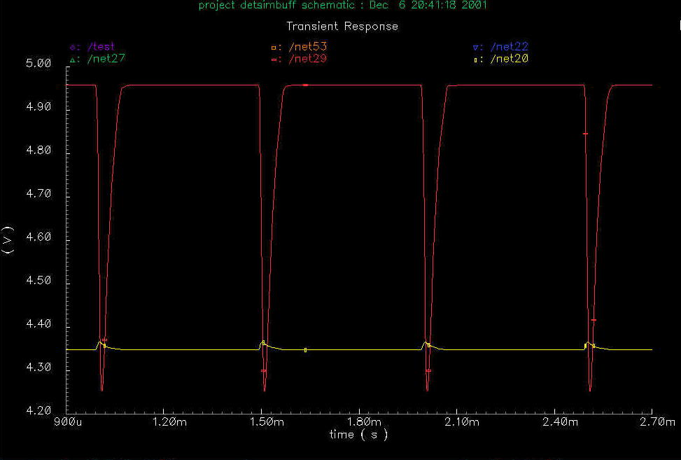
Fig 3.1.2b Magnbification of region showing photodetector
an first inverting amplifier signals.
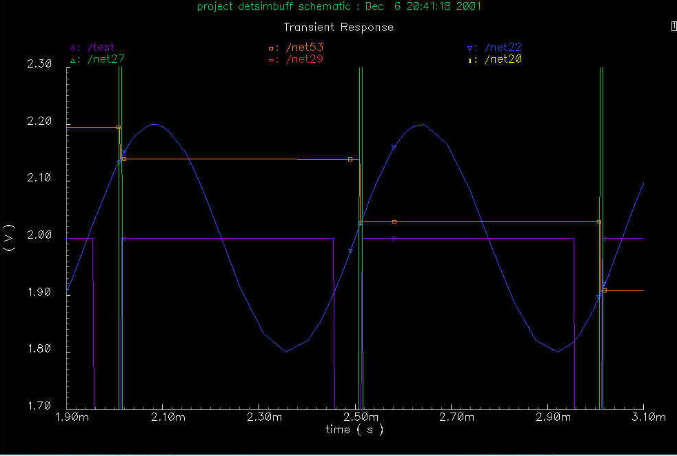
Fig 3.1.2c A more detailed view of the sample and hold
signals. Notice the sample does not trigger until the photocurrent
starts to rise. This corresponds to an overall system offset, and
should not affect performance if it is a consistant effect.
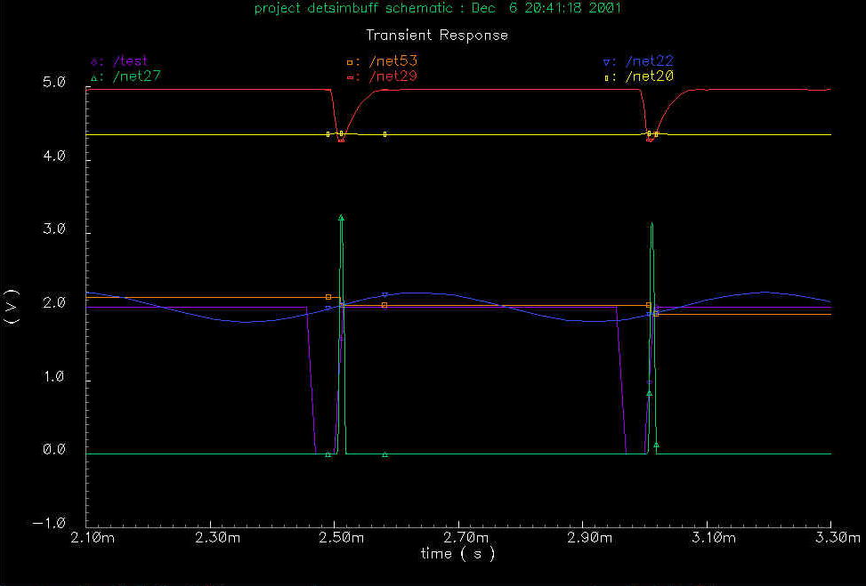
Fig 3.1.2c This shows a set of pulses with greater detail in the time domain.